Manifold Plant
Automatic change-over · 40–300 m³/h · All medical gases
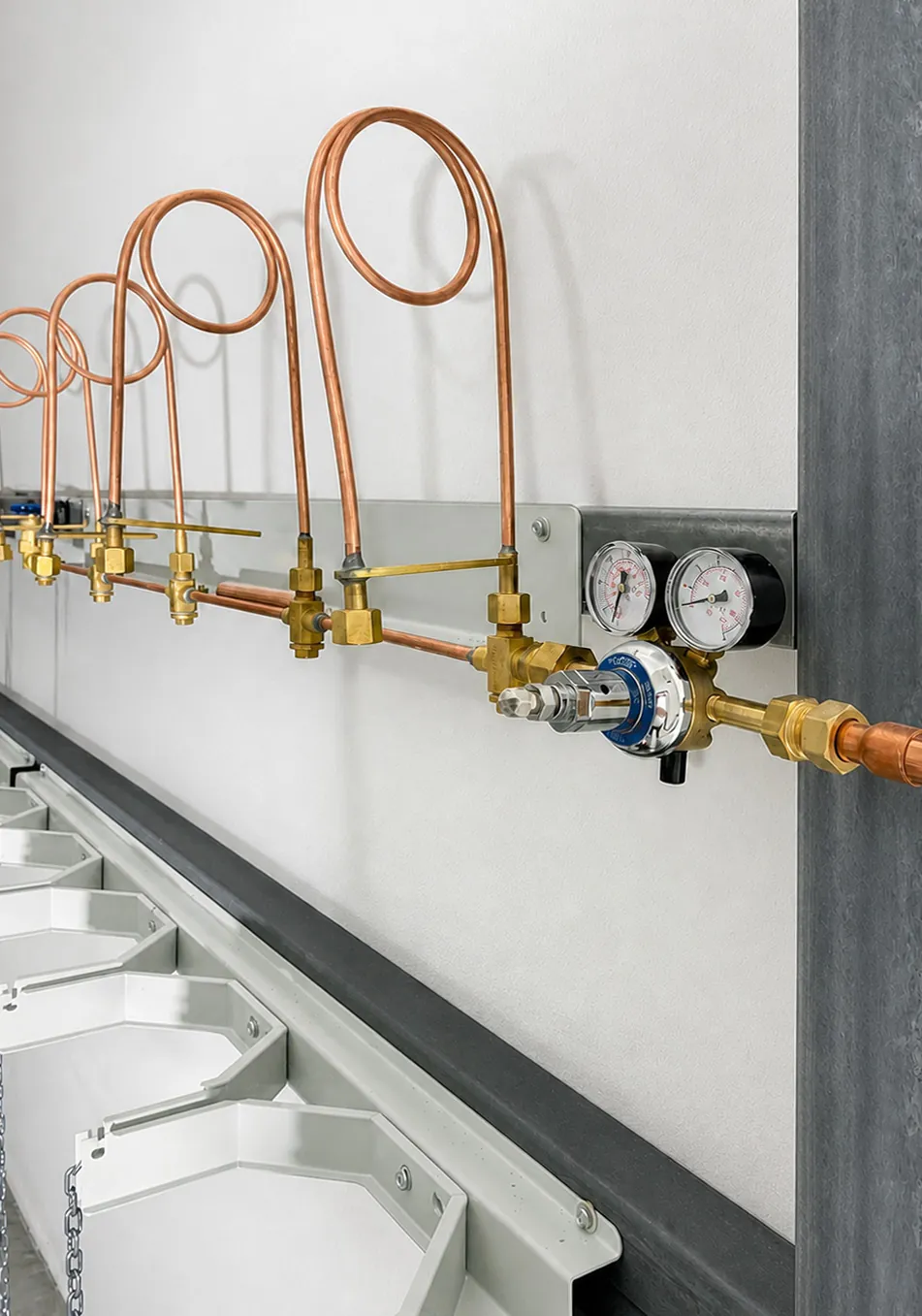
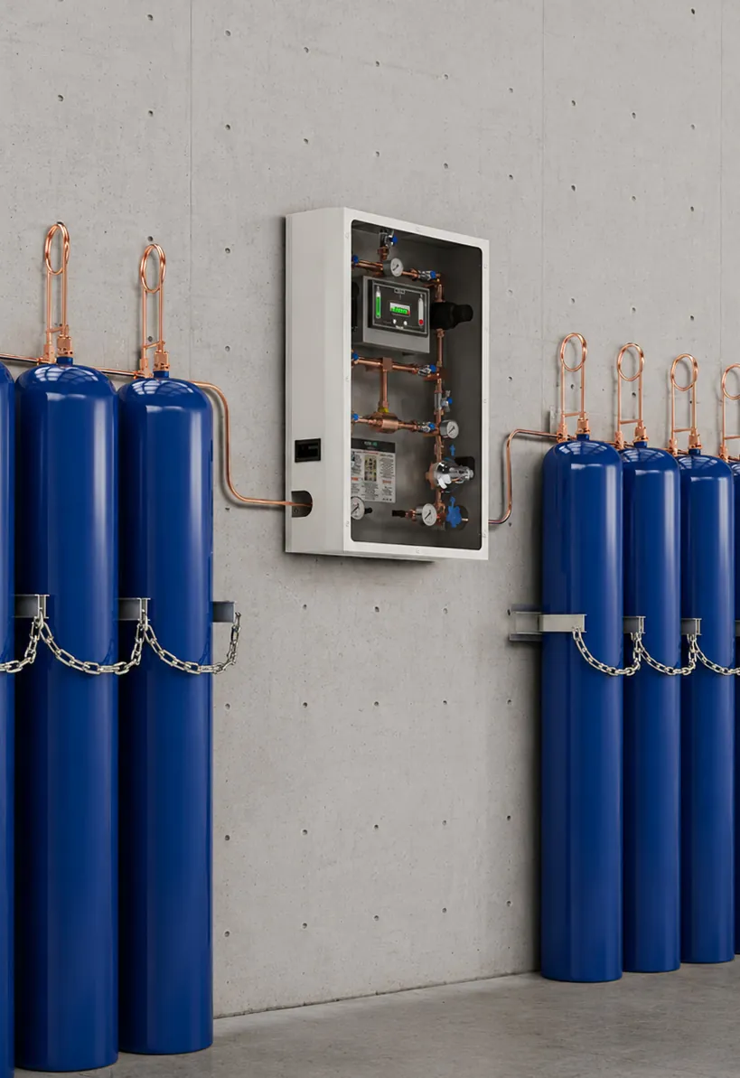
Medical Gas Manifold is a modular gas distribution system designed to provide a continuous gas supply in healthcare facilities. It combines control, pressure regulation, monitoring, and distribution functions within a single system. Compatible with all medical and mixed gases, it delivers stable performance under varying demand conditions.
In addition to new installations, the system is also suitable for projects involving the expansion or modernization of existing medical gas infrastructures.
Standard capacities are available in 40 m³/h and 150 m³/h configurations. Custom-designed systems with capacities up to 300 m³/h can be manufactured to meet specific project requirements.
Gas supply automatically switches to the secondary cylinder bank when the active bank pressure drops. All gas-contacting components are compatible with all medical gases, including oxygen.
The by-pass system maintains continuous gas supply by routing the flow through an alternative line during maintenance and service operations.
KEY FEATURES
- Automatic Change-Over — Continuous gas supply
- High Flow Capacity — 40-300 m³/h range
- Modular Configuration — Project-specific design
- By-Pass System — Uninterrupted maintenance
- Two-Stage Regulation — Stable outlet pressure
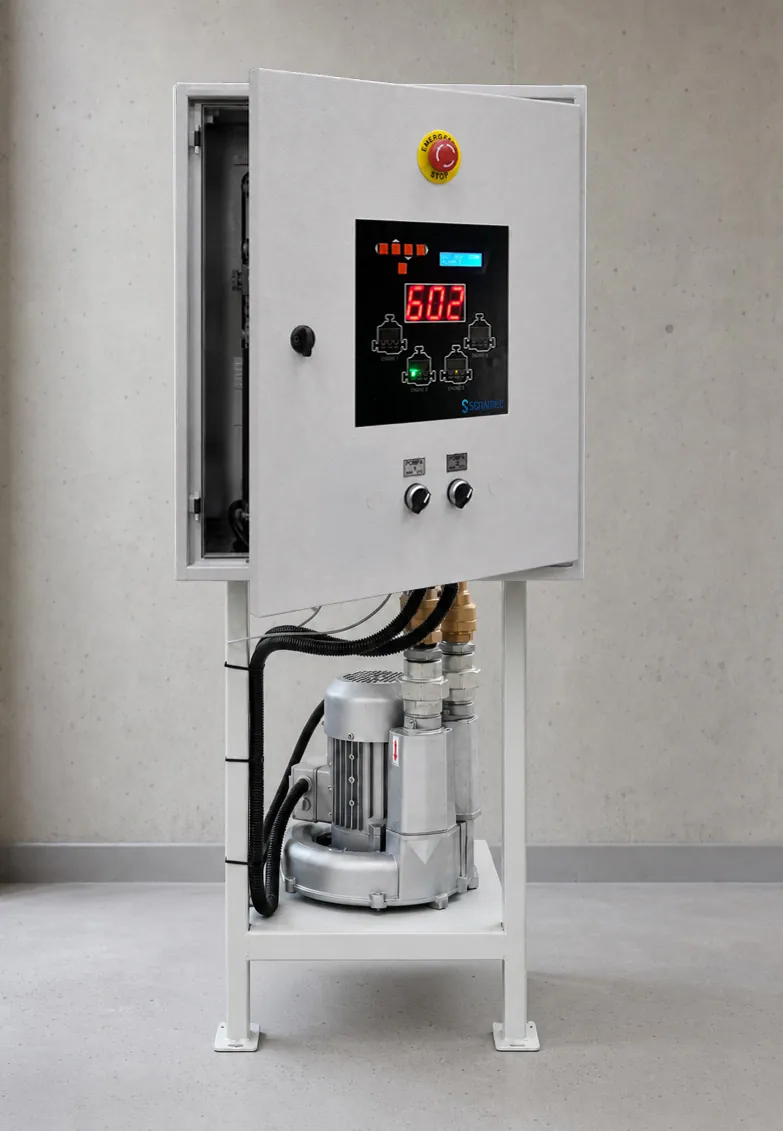
- Alarm Options — Digital or Touchscreen
SYSTEM COMPONENTS
- 01Control & distribution unitMain unit for control, regulation, monitoring and distribution.
- 02Alarm unitMonitors system pressure, raises alarms and reports to the master alarm.
- 03Connection componentsTailpipes and flexible connections between cylinders and header.
- 04Cylinder ramp / headersCollect gas from the cylinders and feed the control panel.
- 05Cylinder holdersSafety units that secure the cylinders in position.
TECHNICAL SPECIFICATIONS
- Supply Voltage
- 220 V, 50 Hz
- Operating Temperature
- (+10) – (+45) °C
- Relative Humidity
- 10–95%
- Capacity
- 40 m³/h and 150 m³/h (up to 300 m³/h according to project requirements)
- Inlet Pressure
- Max. 230 bar
- Outlet Pressure
- 4–12 bar (adjustable)
- Regulation
- Two-Stage Pressure Regulation
- Automatic Change-Over
- Mechanical Change-over / Electronic Solenoid Valve
- Medical Gases
- O₂ – N₂O – MA4 – SA7 – VAC – CO₂ – N₂
- Inlet Lines
- Right and Left Cylinder Banks
- Outlet Line
- Single Outlet Line
- Ramp Options
- Valve / Check-Valve
- Evacuation System
- Separate on Right and Left Lines
- Maintenance / Continuous Operation
- By-Pass Line
- 1st Stage Regulator
- Inlet/Outlet: 230–16 bar
- 2nd Stage Regulator
- Inlet/Outlet: 16–4 bar
- High Pressure Gauge
- 0–230 bar (2 pcs)
- Intermediate Pressure Gauge
- 0–16 bar (2 pcs)
- Line Pressure Gauge
- 0–16 bar (1 pc)
- Control Unit Dimensions (H×W×D)
- 900 × 640 × 232 mm
- Control Unit Housing
- Electrostatic Powder-Coated Mild Steel
- Protective Cover
- Removable Mild Steel Construction with Viewing Window
- Access
- Full Access to All Components Through the Front Cover
- Mounting Type
- Wall or Frame Mounting
- Cylinder Arrangement
- From 1+1 to 30+30 (Project-Specific Configurations Available)
- Module Options
- Single, Double, Triple, Quad, and Quintuple Ramp and Cylinder Holder Modules
- System Structure
- Modular and Expandable
- Quality
- EN ISO 9001:2015 — EN ISO 13485:2016
- Technical and Safety
- EN ISO 7396-1 — EN ISO 7396-2 — EN ISO 9170-1 EN ISO 11197 — EN ISO 15001 — EN 837-1
- Electrical Safety
- EN 60601-1-2
- Labeling
- EN ISO 15223-1 — EN 1041
- Risk Management
- EN ISO 14971
Technical specifications are subject to change without notice. For technical drawings, model codes and all configurations, see the product catalogue (PDF) .